


 PHP with MYSQL Project
 Python Project
 Java/Advanced Java Project
 Asp.net Project
 Data Mining Project
 Cloud Computing Project
 Artificial Intelligence Project
 Arduino Project
 Raspberry Pi Project
 AutoCAD-Civil
 PCB Project
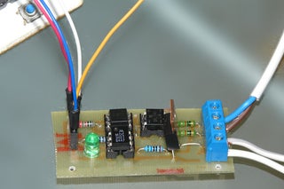
Arduino Controlled Light Dimmer
Apr 21 - 2020
WAIT!! before you decide to build this, it is good to know that a similar dimmer is available at Aliexpress at cost that is hard to beat (currently 2.70 euro)
WARNING: Some people try to build this with an optocoupler with zerocrossing coz 'that is better' right? Some are even told in electronics shops it is better to use such an optocoupler. WRONG. This will only work with a random fire optocoupler: NOT igniting at zerocrossing is the principle of this dimmer.
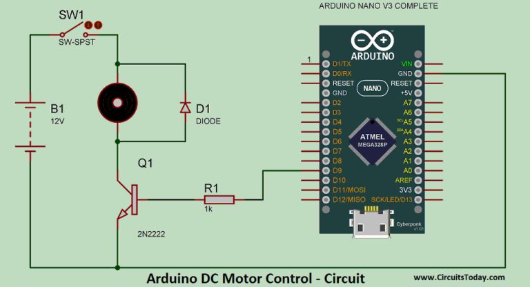
Switching an AC load with an Arduino is rather simpel: either a mechanical relay or a solid state relay with an optically isolated Triac. (I say Arduino, but if you use an 8051 or PIC16F877A microcontroller, there is stuff for you too here.)
It becomes a bit more tricky if one wants to dim a mains AC lamp with an arduino: just limiting the current through e.g. a transistor is not really possible due to the large power the transistor then will need to dissipate, resulting in much heat and it is also not efficient from an energy use point of view.
Phase cutting
One way of doing it is through phase control with a Triac: the Triac then is fully opened, but only during a part of the sinus AC wave. This is called leading edge cutting.
One could let an Arduino just open the Triac for a number of microseconds, but that has the problem that it is unpredictable during what part of the sinus wave the triac opens and therefore the dimming level is unpredictable. One needs a reference point in the sinus wave.
For that a zero crossing detector is necessary. This is a circuit that tells the Arduino (or another micro controller) when the sinus-wave goes through zero and therefore gives a defined point on that sinus wave.
Opening the Triac after a number of microseconds delay starting from the zero crossing therefore gives a predictable level of dimming.
Pulse Skip Modulation
Another way of doing this is by Pulse Skip Modulation. With PSM, one or more full cycles (sinuswaves) are transferred to the load and then one or more cycles are not. Though effective, it is not a good way to dim lights as there is a chance for flickering. Though it might be tempting, in PSM one should always allow a full sinuswave to be passed to the load, not a half sinus as in that case the load will be fed factually from DC which is not a good thing for most AC loads. The difference between leading edge cutting and PSM is mainly in the software: in both cases one will need a circuit that detects the zero crossing and that can control a triac.
A circuit that can do this is easy to build: The zero crossing is directly derived from the rectified mains AC lines – via an optocoupler of course- and gives a signal every time the wave goes through zero. Because the sine wave first goes through double phased rectification, the zero-crossing signal is given regardless whether the sinus wave goes up through zero or down through zero. This signal then can be used to trigger an interrupt in the Arduino.
PWM dimming
PWM dimming, as in LEDs is not done frequently with AC loads for a number of reasons. It is possible though. Check this instructable to see how.
It goes without saying that there needs to be a galvanic separation between the Arduino side of things and anything connected to the mains. For those who do not understand 'galvanic separation' it means 'no metal connections' thus ---> opto-couplers. BUT, if you do not understand 'galvanic separation', maybe you should not build this.
The circuit pictured here does just that. The mains 220Volt voltage is led through two 30k resistors to a bridge rectifier that gives a double phased rectified signal to a 4N25 opto-coupler. The LED in this opto-coupler thus goes low with a frequency of 100Hz and the signal on the collector is going high with a frequency of 100Hz, in line with the sinusoid wave on the mains net. The signal of the 4N25 is fed to an interrupt pin in the Arduino (or other microprocessor). The interrupt routine feeds a signal of a specific length to one of the I/O pins. The I/O pin signal goes back to our circuit and opens the LED and a MOC3021, that triggers the Opto-Thyristor briefly. The LED in series with the MOC3021 indicates if there is any current going through the MOC3021. Mind you though that in dimming operation that light will not be very visible because it is very short lasting. Should you chose to use the triac switch for continuous use, the LED will light up clearly.
Mind you that only regular incandescent lamps are truly suitable for dimming. It will work with a halogen lamp as well, but it will shorten the life span of the halogen lamp. It will not work with any cfl lamps, unless they are specifically stated to be suited for a dimmer. The same goes for LED lamps
NOTE! It is possible that depending on the LED that is used, the steering signal just does not cut it and you may end up with a lamp that just flickers rather than being smoothly regulated. Replacing the LED with a wire bridge will cure that. The LED is not really necessary. increase the 220 ohm resistor to 470 then
STOP: This circuit is attached to a 110-220 Voltage. Do not build this if you are not confident about what you are doing. Unplug it before coming even close to the PCB. The cooling plate of the Triac is attached to the mains. Do not touch it while in operation. Put it in a proper enclosure/container.
WAIT: Let me just add a stronger warning here: This circuit is safe if it is built and implemented only by people who know what they are doing. If you have no clue or if you are doubting about what you do, chances are you are going to be DEAD!DO NOT TOUCH WHEN IT IS CONNECTED TO THE GRID
Materials
Zerocrossing
4N25 €0.25 or H11AA1 or IL250, IL251, IL252, LTV814 (see text in the next step)
Resistor 10k €0.10
bridge rectifier 400 Volt €0.30
2x 30 k resistor 1/2 Watt (resistors will probably dissipate 400mW max each €0.30
1 connector €0.20
5.1 Volt zenerdiode (optional)
Lamp driver
LED (Note: you can replace the LED with a wire bridge as the LED may sometimes cause the lamp to flicker rather than to regulate smoothly)
MOC3021 If you chose another type, make sure it has NO zero-crossing detection, I can't stress this enough DO NOT use e.g. a MOC3042
Resistor 220 Ohm €0.10 (I actually used a 330 Ohm and that worked fine)
Resistor 470 Ohm-1k (I ended up using a 560 Ohm and that worked well)
TRIAC TIC206 €1.20 or BR136 €0.50
1 connector €0.20
Other
Piece of PCB 6x3cm
electric wiring
Apr 21 - 2020

Apr 20 - 2020
Apr 20 - 2020